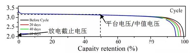
In charge and discharge testing or practical use, the voltage parameters of lithium-ion batteries mainly include platform voltage, median voltage, average voltage, cut-off voltage, etc. The typical discharge curve is shown in Figure 1.
Platform voltage refers to the voltage value corresponding to the minimum voltage change and large capacity change. Lithium iron phosphate and lithium titanate batteries have obvious platform voltages, which can be clearly confirmed in the charge discharge curve. The voltage plateau of most batteries is not obvious. During charge and discharge testing, data is collected through voltage intervals, and the voltage curve is differentiated to determine the plateau voltage through the peak value of dQ/dV.
The median voltage is the voltage value corresponding to half the battery capacity. For materials with obvious plateau, such as lithium iron phosphate and lithium titanate, the median voltage is generally the plateau voltage.
The average voltage is the effective area of the voltage capacity curve (i.e. battery charge/discharge energy) divided by the capacity, calculated as Ü=∫ U (t) * I (t) dt/∫ I (t) dt. In the charging and discharging test data, the average voltage is obtained by dividing the charging or discharging energy by the capacity data. Conversely, battery energy density is also estimated based on the average voltage of the battery, i.e. energy=capacity * average voltage/battery mass (or volume).
Cut off voltage refers to the minimum voltage allowed for battery discharge and the maximum voltage allowed for battery charging. If the voltage is lower than the discharge cut-off voltage and continues to discharge, the potential of the positive electrode of the battery will continue to decrease, while the potential of the negative electrode will rapidly rise, forming over discharge. Over discharge may cause damage to the electrode active material, loss of reaction ability, and shorten the battery life; It can also cause the negative copper foil to decompose and precipitate on the positive electrode, posing a risk of short circuit. If the charging voltage is higher than the charging cut-off voltage, the potential of the positive electrode of the battery continues to rise, causing excessive lithium removal of the positive electrode material, crystal structure damage and failure, and electrolyte decomposition and loss of lithium ions. And the negative electrode potential will continue to decrease, with problems such as excessive lithium insertion, graphite layer disintegration, and lithium deposition on the electrode surface.
Figure 1 Discharge curve of lithium iron phosphate | | graphite battery
In fact, the voltage U of the battery (battery) is determined by the difference between the electrode potential E of the positive electrode (positive electrode) and the electrode potential E of the negative electrode (negative electrode), expressed by formula (1):
U (battery)=E (positive electrode) – E (negative electrode) Equation (1)
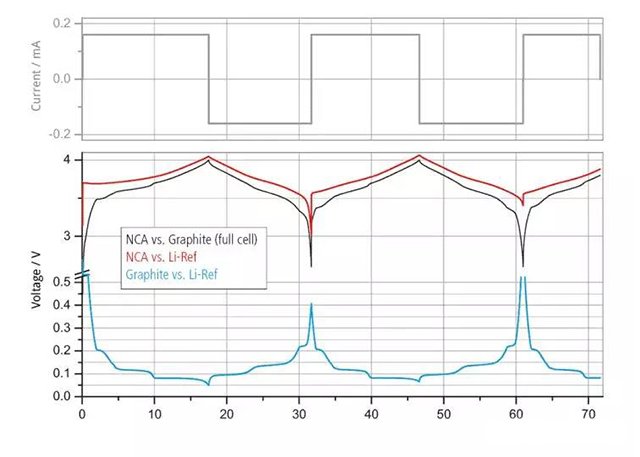
In battery systems, standard lithium electrodes are commonly used as reference electrodes, and the electrode potentials of positive and negative electrode materials are generally generated by the reaction between reactants and products with the reference lithium electrode. As shown in Figure 2, during the charging and discharging process, the positive and negative electrode materials undergo lithium removal or insertion, and the electrode potential changes. The battery voltage is the difference between the two.
Figure 2 Current and voltage curves of a three electrode battery
Therefore, to understand the voltage of a battery, it is necessary to first understand the electrode potential of various electrode materials. Understanding the equilibrium electrode potential curve of the material can better understand the voltage characteristics of the battery.
Open circuit voltage refers to the potential difference between the positive and negative electrodes of a battery when there is no current flowing through the circuit when the battery is not in operation. Assemble the electrode material with metallic lithium to form a button half cell, and the open circuit voltage is the equilibrium potential of the electrode material.
Open circuit voltage testing method
The process of testing the equilibrium potential of electrode materials is as follows: the electrode material is prepared into a polarizer, assembled with metallic lithium to form a button half cell, and the open circuit voltage of the button half cell is measured at different SOC states. The mathematical expression of the open circuit voltage curve is determined using polynomial or Gaussian fitting. The open circuit voltage testing method mainly includes:
- The basic principle of galvanostatic intermittent titration technique (GITT) is to apply a constant current to the measurement system in a specific environment for a period of time, then cut off the current, observe the change of the system potential with time during the applied current period, and the voltage that reaches equilibrium after relaxation (i.e. open circuit voltage). The GITT test example is as follows: (i) Charge at C/50 until the voltage reaches the upper limit voltage, such as 4.2 V; (ii) Let it stand for 2 hours; (iii) Discharge at 1C for 6 minutes and record the discharge capacity; (iv) Let it stand for 15 minutes and record the voltage; (v) Repeat steps (iii) and (iv) 9 times in total; (vi) Discharge at C/50 until the voltage reaches the lower limit voltage, such as 3.0V; (vii) Normalize the capacity voltage curves recorded in steps (iii) and (iv) to create an SOC voltage curve, and fit the mathematical expression of the open circuit voltage curve.
- Low current charge and discharge curve, constant current charge and discharge at a particularly low rate (such as 0.01C), set the upper and lower voltage limits to obtain the low current charge and discharge curve of the battery. Use the point with the same amount of electricity as the starting point of the curve, take the average voltage in the charge and discharge curve, normalize the horizontal axis of the curve according to the theoretical capacity, and then use curve fitting to obtain the open circuit voltage curve.
Battery polarization
The phenomenon of the electrode deviating from the equilibrium electrode potential when current passes through the electrode is called polarization of the battery, which generates overpotential. Polarization can be classified into Ohmic polarization, concentration polarization, and electrochemical polarization based on the causes of polarization, as shown in Figure 2.
Figure 3: The Effect of Current Density on Polarization
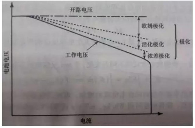
Ohmic polarization: caused by the resistance connecting various parts of the battery, the voltage drop value follows Ohmic’s law. As the current decreases, the polarization immediately decreases and disappears immediately after the current stops.
Electrochemical polarization: Polarization caused by the sluggishness of electrochemical reactions on the electrode surface. As the current decreases, it significantly decreases within microseconds.
Concentration polarization: Due to the slow diffusion process of ions in a solution, polarization occurs at a certain current due to the concentration difference between the electrode surface and the solution itself. This polarization decreases or disappears at the macroscopic level of seconds (several seconds to tens of seconds) as the current decreases.
The internal resistance of the battery increases with the increase of the discharge current, mainly due to the fact that a large discharge current increases the polarization trend of the battery, and the larger the discharge current, the more obvious the polarization trend, as shown in Figure 2. According to Ohm’s Law: V=E0-I × RT, as the overall internal resistance RT increases, the time required for the battery voltage to reach the discharge cut-off voltage also decreases, resulting in a decrease in the discharged capacity.
Lithium ion batteries are essentially a type of lithium-ion concentration battery, and the charging and discharging process of lithium-ion batteries involves the insertion and extraction of lithium ions into and from the positive and negative electrodes. The factors that affect the polarization of lithium-ion batteries include:
2.1 Effects of Electrolyte: Low electrolyte conductivity is the main reason for polarization in lithium-ion batteries. In the general temperature range, the conductivity of the electrolyte used in lithium-ion batteries is generally only 0.01-0.1S/cm, which is one percent of that of aqueous solutions. Therefore, during high current discharge, lithium-ion batteries may not have enough time to replenish Li+from the electrolyte, resulting in polarization phenomenon. Improving the conductivity of the electrolyte is a key factor in enhancing the high current discharge capability of lithium-ion batteries.
2.2 The influence of positive and negative electrode materials: The channel for large lithium ions to diffuse to the surface of positive and negative electrode material particles is lengthened, which is not conducive to high rate discharge.
2.3 Conductive agent: The content of conductive agent is an important factor affecting the high rate discharge performance. If the conductive agent content in the positive electrode formula is insufficient, electrons cannot be transferred in a timely manner during high current discharge, and the polarization internal resistance rapidly increases, causing the battery voltage to quickly drop to the discharge cut-off voltage.
2.4 Effects of Pole Plate Design:
Electrode thickness: In the case of high current discharge, the reaction rate of the active substance is very fast, requiring lithium ions to be able to quickly embed and detach in the material. If the electrode is thick, the diffusion path of lithium ions will increase, and a large lithium ion concentration gradient will be generated in the direction of electrode thickness.
Compaction density: If the compaction density of the electrode is higher and the pores become smaller, the path of lithium ion movement in the thickness direction of the electrode will be longer. In addition, excessive compaction density reduces the contact area between the material and electrolyte, reduces the electrode reaction site, and increases the internal resistance of the battery.
2.5 Impact of SEI film: The formation of SEI film increases the resistance at the electrode/electrolyte interface, causing voltage hysteresis or polarization.
The working voltage of the battery
Working voltage, also known as terminal voltage, refers to the potential difference between the positive and negative electrodes of a battery when there is current flowing through the circuit during operation. In the discharge working state of the battery, when current flows through the inside of the battery, it needs to overcome the resistance caused by the internal resistance of the battery, which will cause ohmic voltage drop and electrode polarization. Therefore, the working voltage is always lower than the open circuit voltage, and the opposite is true during charging, where the terminal voltage is always higher than the open circuit voltage. The result of polarization is that the terminal voltage of the battery is lower than its electromotive force when discharging, and higher than its electromotive force when charging.
Due to the phenomenon of polarization, there may be a certain deviation between the instantaneous voltage and the actual voltage during the charging and discharging process of the battery. During charging, the instantaneous voltage is slightly higher than the actual voltage, and polarization disappears and the voltage drops after charging is completed; During discharge, the instantaneous voltage is slightly lower than the actual voltage, and after discharge, polarization disappears and the voltage rises.
Figure 4 Composition of Battery Voltage and Its Relationship with Operating Current
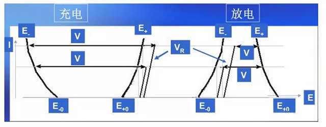
Based on the above, the composition of the battery terminal voltage is shown in Figure 3, and the expression is:
Charging: VCH=(E+- E -)+VR=(E+0+η+) – (E-0- η -)+VR
Discharge: VD=(E+- E -) – VR=(E+0- η+) – (E-0+η -) – VR
Why do some materials have a clear voltage plateau while others do not?
In thermodynamics, the degree of freedom F is a variable that can be independently changed (such as temperature and pressure) when the system is in equilibrium without changing the number of phase states. The number of these variables is called the degree of freedom. The relationship between the degrees of freedom of the system and other variables:
F = C – P + n
Where F: represents the degrees of freedom of the system; C: The number of independent components in the system; P: Number of phases; n: External factors, mostly taken as n=2, represent pressure and temperature.
For the lithium-ion electrochemical system, external factors n=2 are taken as voltage and temperature, respectively. Assuming that the temperature and pressure of lithium-ion electrode materials remain constant during the charging and discharging process. Here, we discuss the binary system (C=2), where if a particle contains a phase, i.e. P=1, then F=1, and the chemical potential is a degree of freedom that varies with lithium concentration (e.g. solid solution lithium cobalt oxide, a phase with constantly changing lithium concentration).
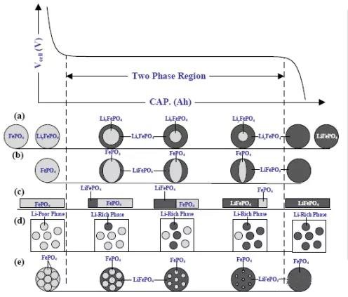
If the particle contains two phases, i.e. P=2, then F=0. When two phases coexist, there exists a flat voltage plateau in a binary electrode material (such as lithium iron phosphate, where the lithium concentration in each phase remains constant).
Figure 5 Schematic diagram of LFP material voltage curve and phase transition process